How to build a Datenzwerg#
Warning
The Datenzwerg was initially developed for the CCCamp23 and later adapted for 37c3. Hardware, firmware and models were chosen and designed for a specific purpose and a specific deployment duration and might not be suitable for other use cases. The Datenzwerg is provided as-is without any warranty, and also for now without any plans to improve or fix it or any other support. If you want to build your own Datenzwerg, you are mostly on your own.
Prerequisites#
Building a Datenzwerg requires some soldering and 3D printing skills.
The firmware provided with the Datenzwerg requires you to provide it with credentials for an existing WiFi network (SSID and password) and also access to an InfluxDB2 instance (host, port, organization id, bucket name and write-enabled access token). You will need to provide these credentials in a file called secrets.yaml in the firmware directory. A template for this file is provided in firmware/secrets-template.yaml.
Parts#
Electronics#
To build your own Datenzwerg, you will need the following parts:
| Count | Item | Function | Link |
|---|---|---|---|
| 1 | Wemos D1 Mini | MCU | AliExpress |
| 1 | BME280 | Environment Sensor | AliExpress |
| 1 | SGP30 | TVOC/eCO2 Sensor | AliExpress |
| 1 | VEML6075 | UV Sensor | AliExpress |
| 1 | ADS1115 | 4 Port ADC | AliExpress |
| 1 | GY-MAX4466 | Sound sensor | Amazon |
| 3 | male 3-pin JST connectors + cables | Sensor & power connectors | Amazon |
| 2 | male 4-pin JST connectors + cables | I2C connector | Amazon |
| 2 | male 8-pin headers, male and female | ESP8266 connector | Amazon |
| 1 | male 10-pin header, male and female | ADS1115 connector | Amazon |
Additionally you'll need a soldering iron, solder, some wires and shrink tubing.
Warning
We use BME sensors. They are often mixed up with the BMP sensors, which lack the humidity sensor. You can identify your module with the help of a picture on this (german) page.
Warning
If you want to battery power your Datenzwerg, do not use the SGP30 sensor. It requires constant power to work properly and will not work with deep sleep. Leave it unpopulated and adjust the firmware config as described below.
Note
We recommend using all parts from the BOM. However, if you want to save money, you can directly solder the sensors to the board and save a little bit on the connectors. You can also save a little bit by skipping the TP4056 and soldering the wires directly to the LiPo. Be warned though that this module provides undervoltage protection to the LiPos.
Gnome body#
If you want to put the Datenzwerg into its gnome body, you will also need:
| Count | Item | Function | Link |
|---|---|---|---|
| 1 | 3D printed gnome body top | Gnome body | Download |
| 1 | 3D printed gnome body bottom | Gnome body | Download (closed) or Download (cable throughholes) |
| 6 | 6x1mm neodymium disc magnets | Connecting the top and bottom of the gnome body | Amazon |
| 1 | ~3mm thick sanded and polished cut-off of a 5mm rod of 0A070GT Plexiglas XT | UV transmissive rain cover for the UV sensor | Sample from the manufacturer |
For assembly you'll also need hotglue, superglue and UV resin.
Note
It is strongly recommended to print the gnome body with a 0.6mm nozzle and 0.4mm layer height. The model is designed for this combination and might not work with other nozzle sizes or layer heights.
With such a setup, print both parts with 3 walls, 3 bottom/top layers, 20% infill and tree supports. The top part should take around 5h to print, the bottom part around 1h.
Hint
We got a 100mm sample rod of the Plexiglas XT from the manufacturer for 3€. We cut it to length with a Dremel and this 3d printed cutting jig, then sanded the cut-off smooth with 240 and 400 grit and polished it with a general polishing compound ("Elsterglanz")2.
Battery power module#
If you want to have the Datenzwerg running on battery power, you will also need:
| Count | Item | Function | Link |
|---|---|---|---|
| 1 | TP4056 | Lipo Charger | AliExpress |
| 1 | 5V MT3608 boost converter | Power supply | AliExpress |
| 1 | 18650 LiPo battery | Power source | (on hand)1 |
| 1 | 18650 LiPo battery holder | Battery holder | Amazon |
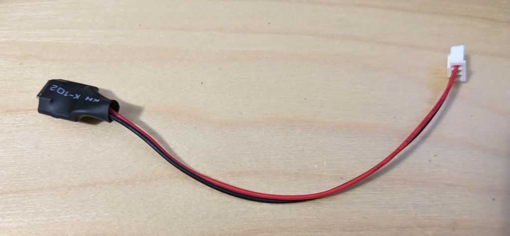
| 1 | male 2-pin JST cable male + JST cable female | Battery cable | Amazon |
MicroUSB power module#
If you want to have the Datenzwerg running on MicroUSB power, you will also need:
| Count | Item | Function | Link |
|---|---|---|---|
| 1 | Micro USB breakout board | Power connector | Amazon |
In that case you should also chose the gnome body bottom with the cable throughholes.
Assembly#
Mainboard#
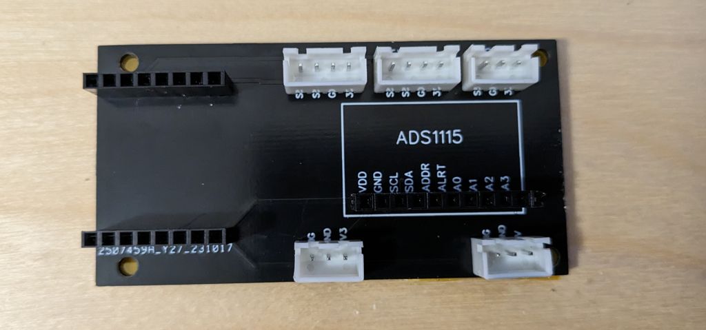
We designed a PCB for the Datenzwerg and got it manufactured. You can find the Gerber files here.
Assembling the Datenzwerg mainboard with such a PCB is quite straightforward. Populate the ENV and TVOC spots with the 4-pin JST headers and the UV, SND and Power spots with the 3-pin JST headers. Then solder two 8-pin headers to the ESP8266 spots and one 10-pin header to the ADS1115 spot.
Then sadly some manual rework is needed: Use a piece of jumper wire and on the underside of the PCB bridge the 3v3 pin of the ESP8266 to the 3v3 pin of either the TVOC or ENV sensor.
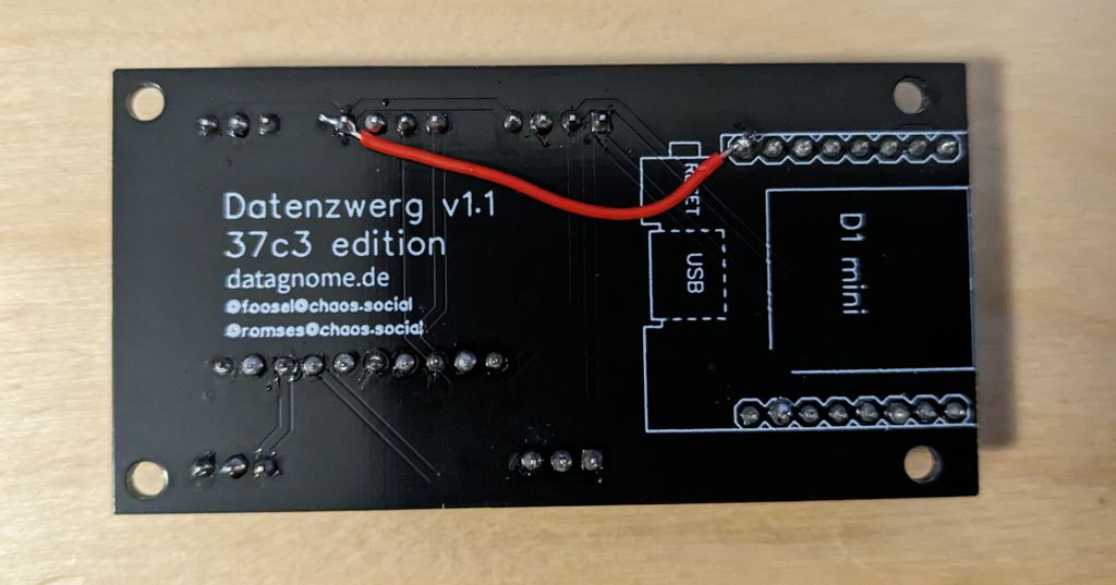
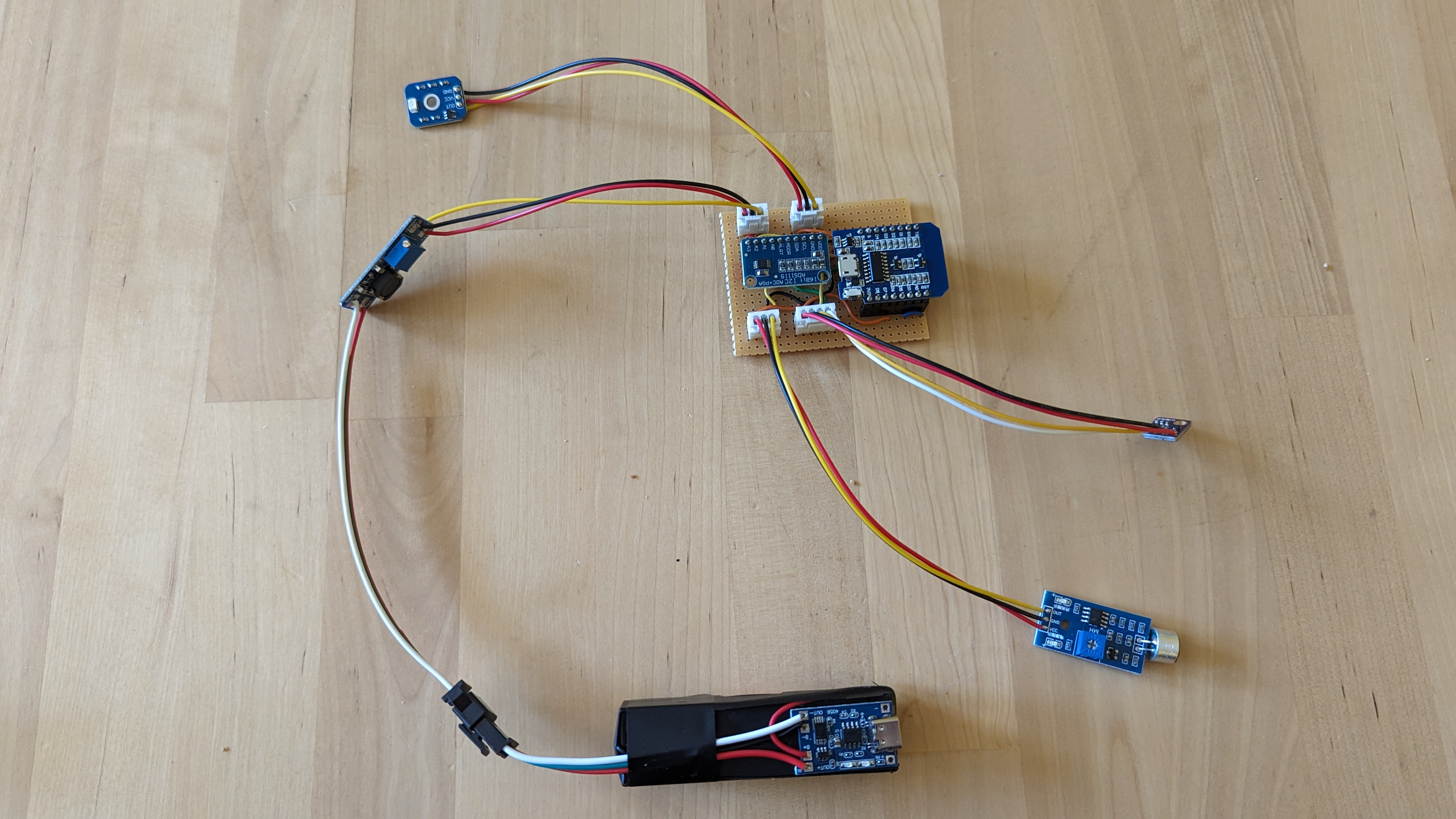
The mainboard is the hardest part to assemble. We recommend to first wire up the 3V3 power trail (orange in the Fritzing drawing) and the GND connections (black), then the I2C trail (green and yellow). Those are the most complex traces. Next do the 5V connections (red) and finally the analogue signals (cyan).
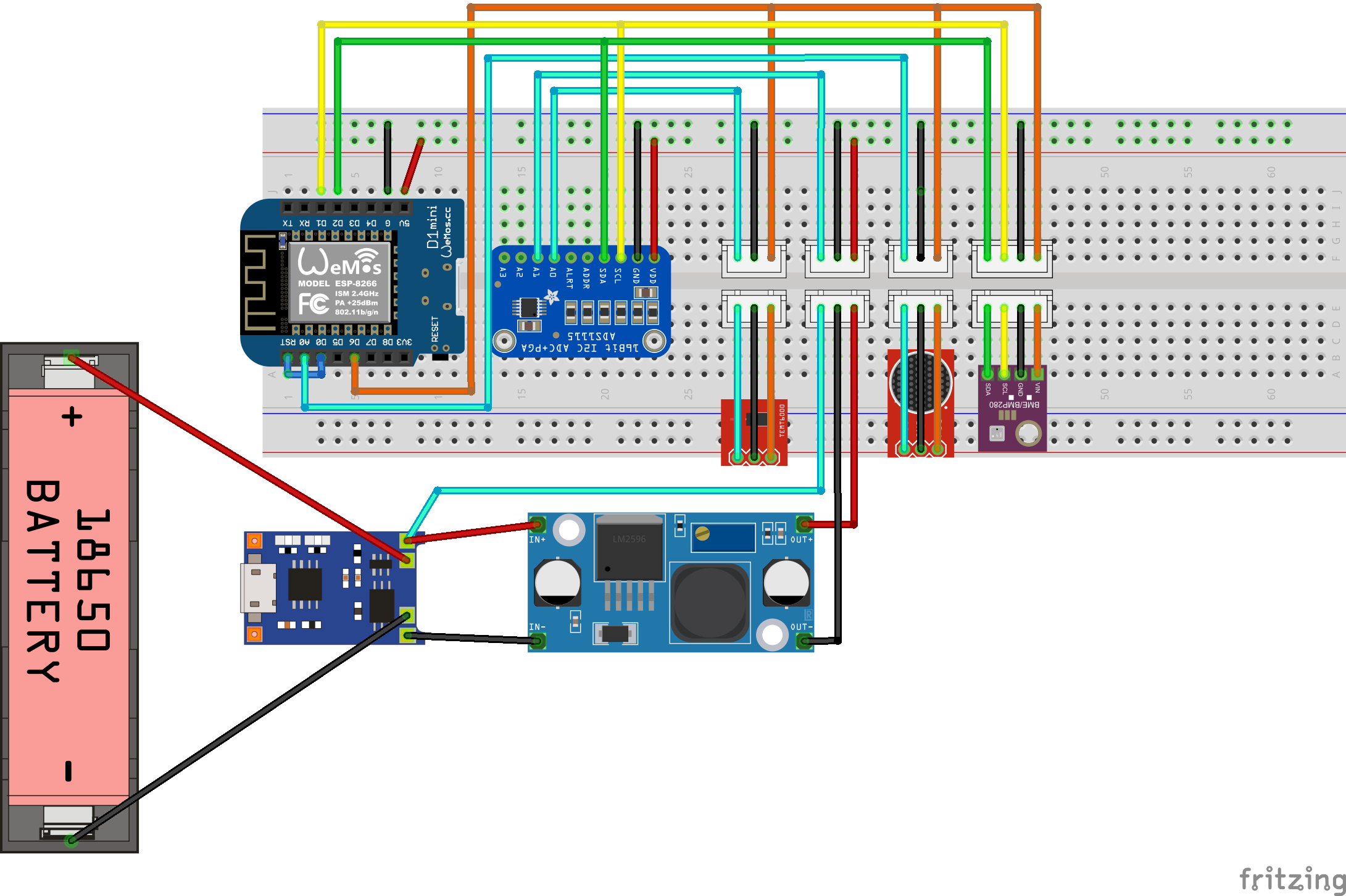
The Fritzing schematic shows the ESP in its original orientation. However, we decided to mount the ESP flipped over. The diagram also shows the ADS1115 in a rotated orientation. This makes the fritzing diagram much easier to understand.

The PCB schematic shows the ESP in the correct orientation as well as the ADS1115. This schematic is much closer to our hand soldered boards than shown in the Fritzing diagram.
Note
We used a special kind of perfboard. The grouping of three pin holes makes organising the wires so much easier.
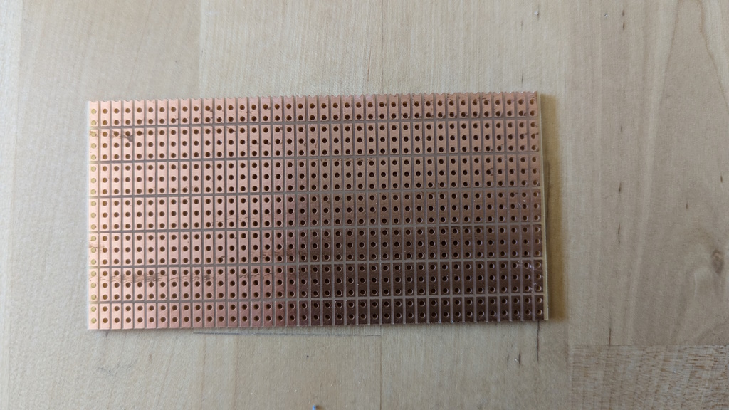
You can find this perfboard on Amazon.
Once you are done soldering up the mainboard, we recommend covering the underside in wide strips of Kapton tape to prevent shorts. Alternatively you may use electric tape.
Note
Things to check after soldering:
- UV sensor, BME280, SGP30 and sound sensor are powered by 3V3 coming from the ESP.
- ADS1115 and ESP are powered by 5V coming from the power supply module.
- All GNDs are connected.
- No shorts between any of the pins, especially between neighbouring pins bridges can quickly happen. Use a multimeter to check for shorts.
Sensors#
UV and sound sensor#
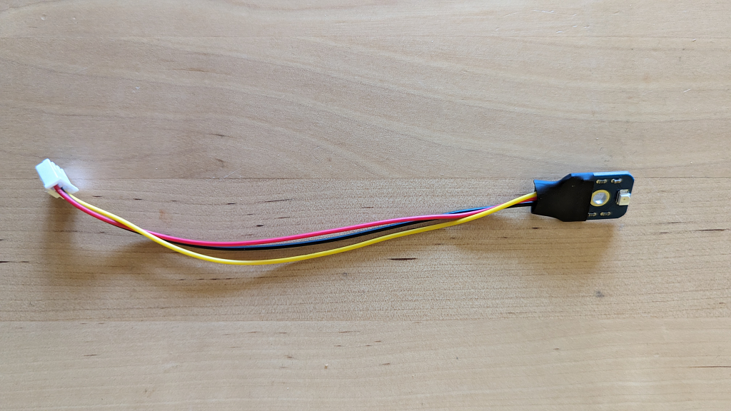
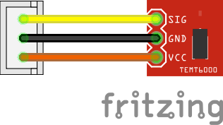
The UV and sound sensors are soldered to JST connector cables to make the sensors replaceable. They share their wiring. Make sure to (carefully!) rotate the potentiometer on the back of the sound sensor to the left-most (clockwise) position, that will set the correct gain of 25x that matches the firmware. Apply shrink tube to protect the soldering joints and reduce the likelihood of shorts.
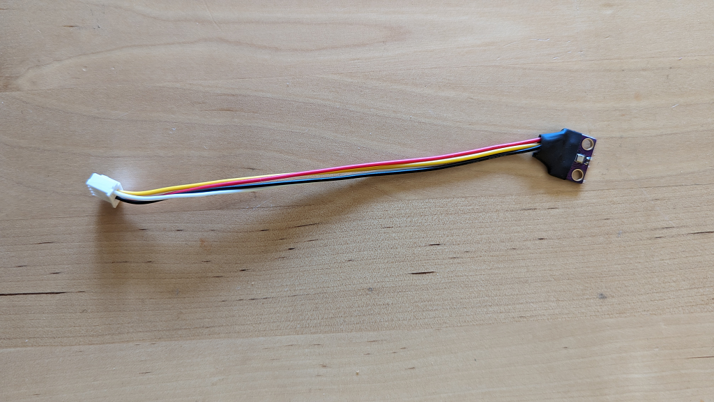
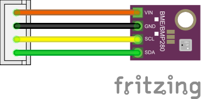
BME280 und SGP30 sensor#
The BME280 and SGP30 sensors are soldered to a 4-pin JST header. Apply shrink tube to protect the soldering joints and reduce the likelihood of shorts.
Note
The temperature inside the Datenzwerg can become much warmer than the outside temperature. We found that even sticking the BME280 outside of the Datenzwerg, by pushing it through the slot on the bottom of the top of the Datenzwerg case, the temperature readings were still extremely high when the Datenzwerg was in direct sunlight, possibly due to radiation of the heated up plastic of the Datenzwerg body. We decided to live with this issue and just note it in the documentation. A different case design could possibly solve this issue.
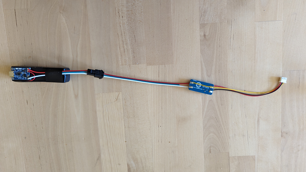
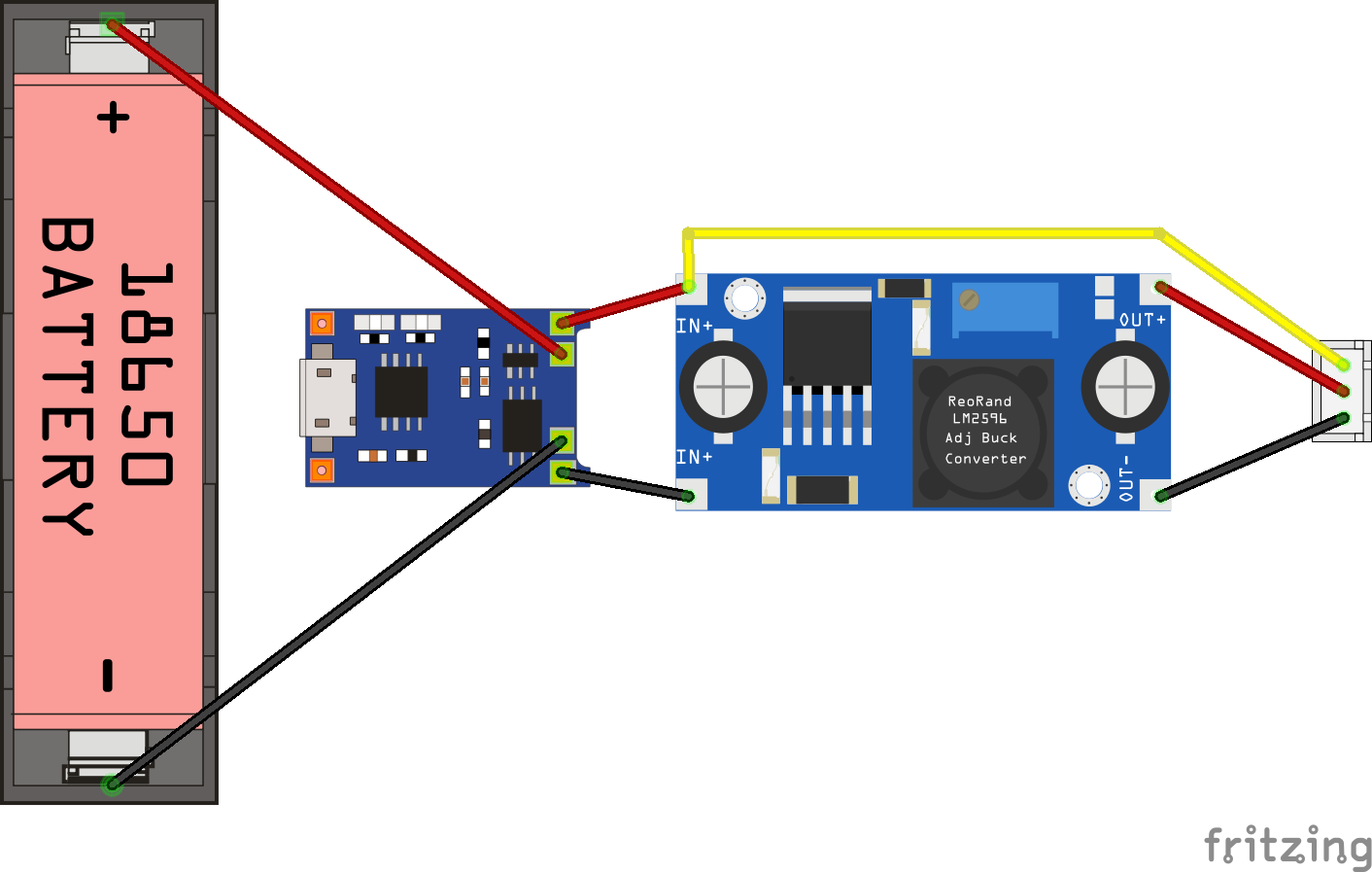
Power supply#
The Power supply is the second complex component of the Datenzwerg.
In our original design it was intended to charge the LiPos directly via the TP4056 modules. However, tests have shown that these modules become very hot during charging - we measured up to 86°C, and that was too high for us to feel good about charging them this way on the possibly very dry field of the CCCamp.
Therefore, we charge the LiPos externally in an off-the-shelf LiPo charger. We however kept the modules to prevent deep discharge.
The BAT+ and BAT- terminals are connected to VIN+ and VIN- of boost converters set to 5V output voltage. Both the ADS1115 and the ESP8266 could be operated with 3V3. However, the TP4056 module supplies battery voltage. Therefore, the easiest way was to boost the voltage to 5V using a boost converter to power both the ESP8266 and the ADS1115. This has also the added advantage of allowing us to measure the battery voltage using the ADS1115, which is able to measure voltages up to Vcc + 0.3V. We therefore connected the third wire of the 3-pin JST header used for the connection to the mainboard to VIN+, with the other two wires connected to VOUT+ and VOUT-.
Shrink tube is applied to protect the soldering joints and reduce the likelihood of shorts.
The MicroUSB power module is much simpler than the battery power module. It is simply a MicroUSB breakout board soldered to a 3-pin JST header, red to 5V, black to GND, the yellow sensor cable is cut off. Shrink tube is applied to protect the soldering joints and connector and reduce the likelihood of shorts.
Gnome body#
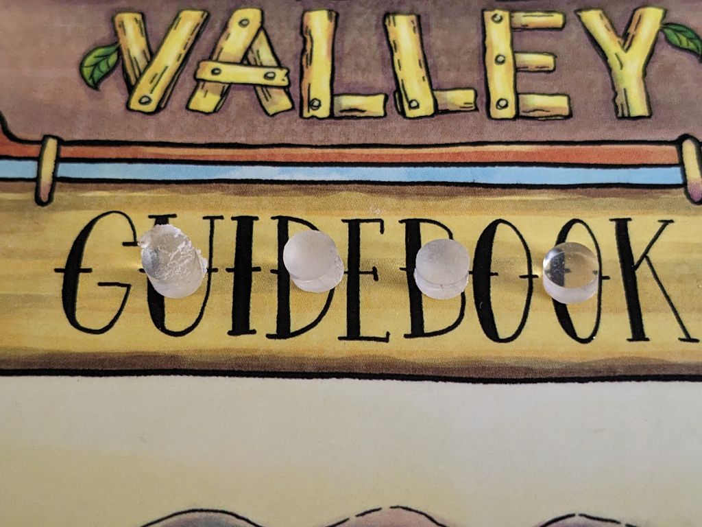
Using superglue, glue the magnets into the holes in the gnome body - there are three each on the mating surfaces of top and bottom part. Make sure the polarity is correct, i.e. the magnets attract each other when the gnome body top is placed on the bottom. The magnets should be flush with the surface.
Fit the acrylic rain cover into the hole in the hat. If it won't fit right away, carefully sand the print until it does. It should be flush with the inner surface of the gnome body, it's ok if it protrudes a bit on the front. Carefully - making really sure to not get any on the central surface of the acrylic disc - apply UV resin around the edges of the rain cover. Then cure it with a UV lamp.
Warning
Make sure to not get any UV resin on the surface of the acrylic disc. If you do, it will be permanently fogged up.
Use a small screwdriver or other tool to hold the UV sensor in place with its shrink tubing. Apply hot glue on the shrink tubing and then press the sensor into its final position so that the sensor is centered inside the acrylic window.
Apply hot glue the same way to the shrink tubing of the BME sensor and place it right next to the slot in the lower part of the gnome body top, with the sensor facing downwards.
Flashing the firmware#
Make sure the power is disconnected from the Datenzwerg's mainboard. Unplug the D1 mini from the mainboard and connect it to your computer via USB.
Install Python 3.11. Check out the GitHub repository and therein run
python -m venv venvsource venv/bin/activatepip install -r requirements.txt
This will install all dependencies needed to build the firmware and the documentation into a virtual environment and activate it.
Then, navigate to the firmware directory. Copy secrets-template.yaml to secrets.yaml and fill in your WiFi, MQTT and InfluxDB2 credentials and also set an OTA password if wanted. Make desired adjustments of packages to be compiled in in datenzwerg.yaml. Then run
esphome -s name <gnome> -s eco2_baseline <eco2 baseline> -s tvoc_baseline <tvoc baseline> run datenzwerg.yaml
<gnome> with the eCO2 baseline <eco2 baseline> and the TVOC baseline value <tvoc baseline>.
E.g. if you want to flash the firmware for the gnome named zwerg with eCO2 baseline 0x7F10 and TVOC baseline 0x88B4, run esphome -s name zwerg -s eco2_baseline 0x7F10 -s tvoc_baseline 0x88B4 run datenzwerg.yaml. If you don't yet have baseline values, you can leave them out: esphome -s name zwerg run datenzwerg.yaml.
Warning
The checked in version of the firmware is currently optimized for v1.1 with MicroUSB powered deployment, as the TVOC sensor added in v1.1 requires constant power for sensible readings.
If you want to use the firmware with a battery powered Datenzwerg, you will need to adjust the firmware config to enable deep sleep by removing the comment in front of the deepsleep package in firmware/datenzwerg.yaml and commenting out the tvoc and uptime packages:
packages:
  base: !include packages/base.yaml # base v1.0 sensor package
  #tvoc: !include packages/tvoc.yaml # TVOC sensor added in v1.1, incompatible to battery power
  deepsleep: !include packages/deepsleep.yaml  # enable this on battery power
  #uptime: !include packages/uptime.yaml  # disable this on battery power

  # these should not be enabled in production
  #ota: !include packages/ota.yaml
  #webserver: !include packages/webserver.yaml
If you do not compile with the TVOC package included, you can leave out the eco2_baseline and tvoc_baseline parameters during compilation.
Plug the D1 mini back into the mainboard and reconnect the power. It should connect to your WiFi and start sending data to the configured InfluxDB.
-
We sourced our LiPo batteries from some old USB power banks we happened to have. ↩
-
We did this by holding the disc with pliers. For sanding, we pressed it against a disc sander on the lowest setting, with the right grit. For polishing, we rubbed it manually again and again on a microfibre cloth with the polishing compound applied, lying on top of a flat hard surface. Don't forget to do both sides! ↩